
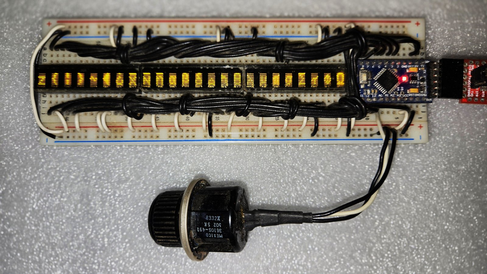
This section documents the original sketch. The rewrite repo uses the same wiring and scroll logic; see new_3_bank_display_test for that README.
Overview
This program drives three PDSP1880 LED character displays from an OSEPP Pro Mini (Atmel ATmega328 at 5 V, 16 MHz). The three modules are wired as one master and two slaves so they act as one long chain of digit positions.
The firmware walks the full displayable ASCII set (TotalDisChar = 0x7F) across every digit. Characters are written left to right: DisPosCount advances until TotalDig is reached, then the run returns to the leftmost digit and the character index advances by one. That continues until TotalDisChar + TotalDig - 1 is reached.
Conditional math between Char2Count and Char2Dis corrects for the offset caused by writing left-to-right across TotalDig positions. Extra wrap math at the end of the character set makes the sequence roll from the last glyph back to the first so the chain never stops with a hard edge.
Scroll speed comes from analog pin A0 (pot wiper). The ADC reading is scaled with map() into a delay Timeinms between 20 ms and 500 ms. At shorter delays the full ASCII run looks like the character set is scrolling right to left.
Hardware
| Item | Detail |
|---|---|
| MCU | OSEPP Pro Mini - ATmega328 @ 5 V, 16 MHz |
| Displays | 3× PDSP1880 (left master + two slaves) |
| Scroll control | Potentiometer wiper on A0 (CCW = GND, CW = +5 V; sketch notes a 10 kΩ ten-turn) |
| Power | +5 V (VIN) and GND to the Pro Mini and all three displays |
How the firmware works
Setup
setup() sets Port D and Port B as outputs (DDRD / DDRB = 0xFF), then loads Port D with ASCII space (0x20) so the displays power up blank instead of showing garbage.
Main loop
Each pass of loop():
- Adjusts
Char2Countif it has already walked pastTotalDig(offset after the first full pass across the chain). - For every digit position
DisPosCountfrom0throughTotalDig(0x17= 23):- Holds /WR idle high (
DisIdle | Char2Dis) so nothing is written while the next glyph is prepared. - Computes
Char2DisfromChar2Count, wrapping when the count passesTotalDisChar. - Advances
Char2Count, or resets it to0at the end of the wrap window. - Reads the pot on A0 and updates
Timeinms(ScrMin…ScrMax). - Selects the bank (left / mid / right module) from
DisPosCount. - Writes bank + digit address on Port B, then pulses the character out on Port D with /WR low (
DisWR | Char2Dis).
- Holds /WR idle high (
- After all digits are updated,
delay(Timeinms)sets how long that frame holds before the next character step.
Bank select
| Digit positions | Bank value | Module |
|---|---|---|
| 0-7 | 0xF0 | Left (bank 1, D11) |
| 8-15 | 0xE8 | Middle (bank 2, D12) |
| 16-23 | 0xD8 | Right (bank 3, D13) |
PORTB = Bank | DisPosCount combines chip-enable bits with the digit address on A0-A2 (D8-D10).
Schematic
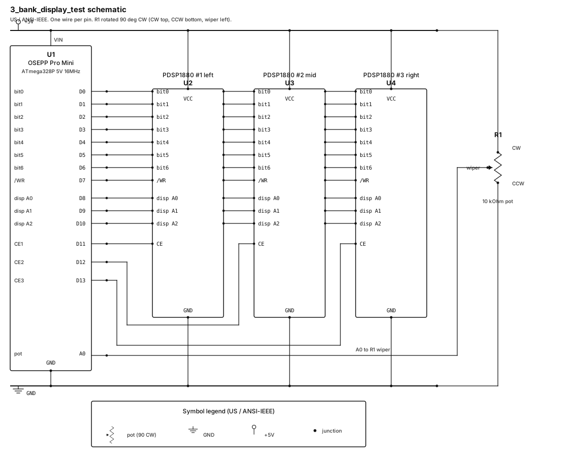
Shared bit0-bit6, /WR, and disp A0-A2 go to all three PDSP1880 modules. D11 / D12 / D13 are individual bank selects (CE1-CE3). The pot wiper goes to A0.
Pin map
From the sketch header. Port D is character data and write; Port B is digit address and bank select.
| Pro Mini | Port | Chip pin # | Function |
|---|---|---|---|
| D0 (RX0) | PD0 | 30 | Display bit 0 |
| D1 (TX1) | PD1 | 31 | Display bit 1 |
| D2 | PD2 | 32 | Display bit 2 |
| D3 | PD3 | 1 | Display bit 3 |
| D4 | PD4 | 2 | Display bit 4 |
| D5 | PD5 | 9 | Display bit 5 |
| D6 | PD6 | 10 | Display bit 6 |
| D7 | PD7 | 11 | Display write (active low) |
| D8 | PB0 | 12 | Display A0 |
| D9 | PB1 | 13 | Display A1 |
| D10 | PB2 | 14 | Display A2 |
| D11 | PB3 | 15 | Bank select 1 (left) |
| D12 | PB4 | 16 | Bank select 2 (middle) |
| D13 | PB5 | 17 | Bank select 3 (right) |
| A0 | PC0 | 23 | Scroll-speed pot wiper |
| VIN | - | - | +5 V |
| GND | - | - | Ground |
| RST | - | - | Reset |
| NC | - | - | No connection |
Build and upload
- Clone or download 3_bank_display_test from GitHub.
- Open the sketch file
Three_bank_display_testin the Arduino IDE (no external libraries required). - Select board Arduino Pro or Pro Mini, processor ATmega328P (5 V, 16 MHz).
- Wire as in the schematic / pin map above.
- Upload and turn the pot to adjust scroll speed.
GitHub Actions compiles this sketch on every push to master (compile check only; does not upload to the board).
Original sketch: Jim Burney, July 2013.